How to Read and Write to Bno080
Introduction
Bosch's BNO080 is a combination triple axis accelerometer/gyro/magnetometer packaged with an ARM Cortex M0+ running powerful algorithms. The BNO080 Inertial Measurement Unit (IMU) produces accurate rotation vector headings, excellently suited for VR and other heading applications with a static rotation error of 2 degrees or less. It'south what nosotros've been waiting for: all the sensor data is combined and drift corrected into meaningful, accurate IMU information. It'southward perfect for whatever project that needs to sense orientation or motion. We've taken this IMU and stuck it on a Qwiic enabled breakout board, in gild to make interfacing with the tiny, QFN package a bit easier to connect.
In this hookup guide, we'll connect our sensor up to our microcontroller of choice and separately read the rotation vectors (which is what we will mainly want), dispatch vectors, gyro values, and magnetometer vectors. We'll check out how to implement the step counter on the BNO080 in order to use information technology as a pedometer. Nosotros'll too read Q values and diverse other metadata from the sensor. Knowing what activity y'all're performing is important so we'll learn how to classify what action the IMU is performing (i.e. Sitting however, moving, biking, walking, running, etc...) and how confident the IMU is that each activity is being performed. The examples will also show how to calibrate our hardware to requite us the near accurate readings possible. Printing out raw packets will too be examined for debugging purposes. Finally, we'll examine how to configure the sensor on dissimilar ItwoC ports and addresses. A bonus example is provided in Processing to testify the states how to use quaternion data to orient a cube.
Required Materials
To get started, you'll need a microcontroller to, well, command everything.
SparkFun ESP32 Matter
DEV-13907
The SparkFun ESP32 Thing is a comprehensive development platform for Espressif's ESP32, their super-charged version of the …
Raspberry Pi 3
DEV-13825
Everyone knows and loves Raspberry Pi, but what if you didn't need additional peripherals to brand it wireless. The Raspberry …
Retired
At present to go into the Qwiic ecosystem, the fundamental will exist one of the following Qwiic shields to match your preference of microcontroller:
You will likewise need a Qwiic cable to connect the shield to your accelerometer, choose a length that suits your needs.
Qwiic Cable - 100mm
PRT-14427
This is a 100mm long 4-conductor cable with 1mm JST termination. It's designed to connect Qwiic enabled components together…
Qwiic Cable - 500mm
PRT-14429
This is a 500mm long 4-conductor cable with 1mm JST termination. It's designed to connect Qwiic enabled components together…
Qwiic Cable - 50mm
PRT-14426
This is a 50mm long 4-conductor cable with 1mm JST termination. Information technology's designed to connect Qwiic enabled components together …
Qwiic Cablevision - 200mm
PRT-14428
This is a 200mm long 4-usher cable with 1mm JST termination. Information technology's designed to connect Qwiic enabled components together…
Suggested Reading
If you lot aren't familiar with the Qwiic system, we recommend reading here for an overview.
We would also recommend taking a expect at the following tutorials if yous aren't familiar with them. We also delve into Processing in this tutorial, if yous aren't familiar, check out the below tutorial on Processing.
Serial Communication
Asynchronous serial communication concepts: packets, signal levels, baud rates, UARTs and more!
Gyroscope
Gyroscopes mensurate the speed of rotation around an axis and are an essential part in determines ones orientation in space.
I2C
An introduction to I2C, one of the main embedded communications protocols in use today.
Hardware Overview
Allow's expect over a few characteristics of the BNO080 sensor so we know a bit more virtually how information technology behaves.
| Characteristic | Range |
|---|---|
| Operating Voltage | 1.65V - iii.6V |
| Linear Acceleration Accurateness | ±.35m/southii |
| Gyroscope Accuracy | ±.35m/south2 |
| I2C Accost | 0x4B (S0 Pulled High) or 0x4A (S0 grounded) |
Pins
There are multiple rows of pins on the BNO080, the commencement row, used for the default I2C interface (configurable upward to 400 kHz) is explained in the table below.
| Pin Label | Pin Office | Input/Output | Notes |
|---|---|---|---|
| PS0 | Protocol Selection | Input | Configuration of the communication interface (Default: 0, I2C) |
| PS1 | Protocol Option | Input | Configuration of the communication interface (Default: 0, I2C) |
| GND | Basis | Input | 0V/mutual voltage. |
| 3V3 | Power Supply | Input | Should exist betwixt 1.65 - 3.6V |
| SDA | IiiC Information Signal | Bi-directional | Bi-directional information line. Voltage should non exceed power supply (east.chiliad. 3.3V). |
| SCL | ItwoC Clock Signal | Input | Clock signal. Voltage should not exceed power supply (due east.g. iii.3V). |
| RST | Reset Bespeak | Input | Reset point, active low, pull low to reset IC |
| INT | Interrupt | Output | Interrupt, active depression, pulls depression when the BNO080 is ready for advice. |
Also broken out on the board is a Series Peripheral Interface (SPI) which can run data up to 3MHz. The pins for this interface are outlined below. On any pin, the voltage should not exceed that supplied on the 3V3 pin.
Notation: Yous may not recognize the COPI/CIPO labels for SPI pins. SparkFun has joined with other members of OSHWA in a resolution to movement away from using "Principal" and "Slave" to describe signals between the controller and the peripheral. Check out this page for more on our reasoning backside this change. You lot can besides encounter OSHWA'southward resolution hither.
| Pivot Characterization | Pin Office | Input/Output | Notes |
|---|---|---|---|
| GND | Basis | Input | 0V/Common Voltage |
| 3V3 | Power | Input | Should be between 1.65 - 3.6V |
| SCK | Clock | Input | Clock indicate to synchronize controller and peripheral. |
| SO | CIPO | Output | Controller in, peripheral out. Device sends data to the controller on this line. |
| SI | COPI/ADDR | Input | Controller out, peripheral in. Device receives data from the microcontroller on this line. Necktie to three.3V to change I2C accost from 0x4A to 0x4B |
| CS | Chip Select | Input | Chip select, active low, used as flake select on SPI |
| WAK | Wake | Input | Active low, Used to wake the processor from a sleep style. |
| RST | Reset Signal | Input | Reset betoken, active low, pull low to reset IC |
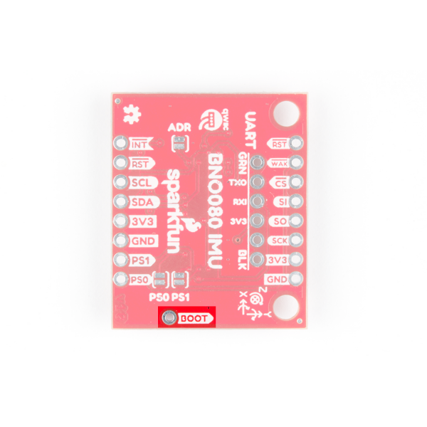
You can likewise utilize the UART interface at up to 3 Mbps or a simplified UART called UART-RVC (Used for robotic vacuum cleaners) which can run at a data rate of 115200 kbps. The UART interface is in the heart of the board, with the black and light-green pins labeled on the back of the board as shown below. These serial pins have been arranged to work with our Serial Basic board to make interfacing to a computer simple and fast. The GRN and BLK labels assist align the serial connection properly.
Also note the Kick pin next to the Qwiic connector, which is necessary for configuration of the communication mode. If the Kick pin is depression upon reset or ability up, the scrap will go into bootloader fashion to allow for programming of new firmware.
Optional Features
Pull-Up Resistor Jumper
The Qwiic VR IMU has onboard I2C pull upwardly resistors; if multiple sensors are connected to the bus with the pull-upwards resistors enabled, the parallel equivalent resistance will create too strong of a pull-up for the coach to operate correctly. Equally a full general dominion of thumb, disable all but ane pair of pull-up resistors if multiple devices are connected to the jitney. If you need to disconnect the pull upwards resistors they can be removed past removing the solder on the corresponding jumpers highlighted below.
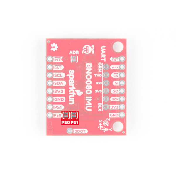
Protocol Selection Jumpers
You can use the PS0 and PS1 jumpers to modify the advice protocol that the BNO080 is using. The jumpers are left open up (0) by default, and the following configurations will let for their corresponding communications protocols.
| PS0 | PS1 | Interface |
|---|---|---|
| 0 | 0 | I2C |
| 1 | 0 | UART-RVC |
| 0 | 1 | UART |
| 1 | ane | SPI |
The jumpers themselves are located on the back of the lath, shown below
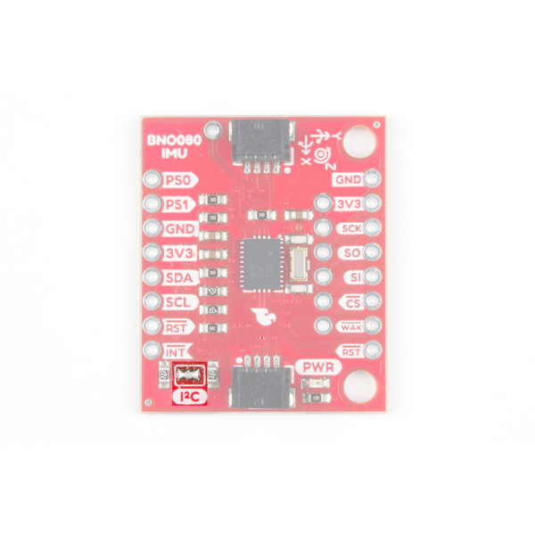
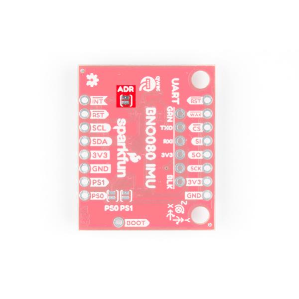
ItwoC Jumper
You lot can too change the address of the BNO080 from 0x4B (default) to 0x4A by connecting the I2C ADR jumper. The jumper itself is shown in the beneath image.
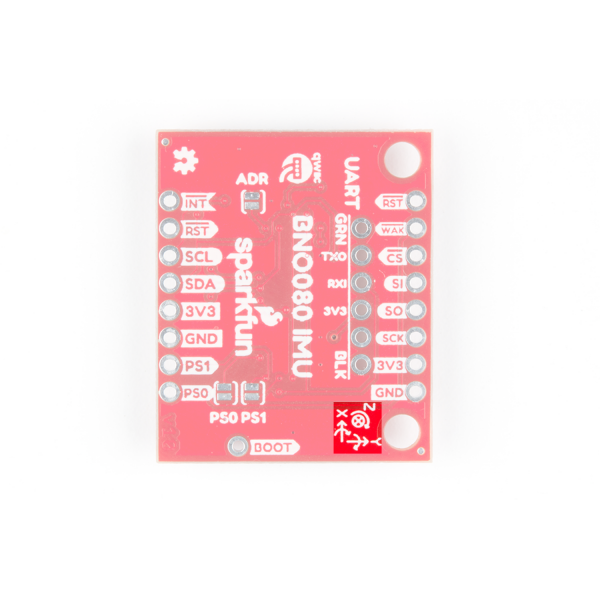
Axis Reference
Also, be sure to bank check out the labeling on the front of the lath that indicates the orientation of the positive X, Y, and Z axes and so yous know which way your data is pointing.
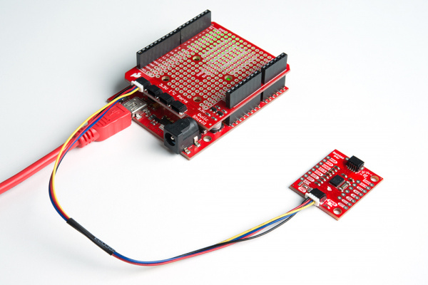
Hardware Associates
If you haven't yet assembled your Qwiic Shield, at present would be the time to head on over to that tutorial. With the shield assembled, SparkFun's new Qwiic environment means that connecting the sensor could not be easier. But plug one end of the Qwiic cablevision into the BNO080 breakout, the other into the Qwiic Shield of your option and you'll be ready to upload a sketch and figure out how you're moving that board. It seems like it's too piece of cake too use, but that's why we fabricated it that way!
Library Overview
Annotation: This case assumes you are using the latest version of the Arduino IDE on your desktop. If this is your beginning time using Arduino, please review our tutorial on installing the Arduino IDE. If y'all have not previously installed an Arduino library, please cheque out our installation guide.
Before we get into programming our IMU, let's download and check out the bachelor functions in our library. SparkFun has written a library to control the Qwiic VR IMU. You tin obtain these libraries through the Arduino Library Manager. Search for SparkFun BNO080 Cortex Based IMU and you should be able to install the latest version. If you adopt manually downloading the libraries from the GitHub repository, y'all can take hold of them here:
Let'southward get started by looking at the functions that set upwardly the IMU.
Setup and Settings
-
boolean begin(uint8_t deviceAddress = BNO080_DEFAULT_ADDRESS, TwoWire &wirePort = Wire);--- By default use the default I2C address, and utilize Wire port, otherwise, pass in a custom I2C address and wire port. -
void enableDebugging(Stream &debugPort = Series);--- Plow on debug press. If user doesn't specify method of printing then Serial will be used. -
void enableRotationVector(uint16_t timeBetweenReports);--- Enables the rotation vector to give a written report everytimeBetweenReportsms. -
void enableGameRotationVector(uint16_t timeBetweenReports);--- Enables the game rotation vector to give a study everytimeBetweenReportsms. -
void enableAccelerometer(uint16_t timeBetweenReports);--- Enables the accelerometer withtimeBetweenReportsin ms. -
void enableGyro(uint16_t timeBetweenReports);--- Enables the gyroscope withtimeBetweenReportsin ms. - **
void enableMagnetometer(uint16_t timeBetweenReports);--- Enables the magnetometer withtimeBetweenReportsin ms. -
void enableStepCounter(uint16_t timeBetweenReports);--- Enables the step counter withtimeBetweenReportsin ms. -
void enableStabilityClassifier(uint16_t timeBetweenReports);--- Enables the stability classifier withtimeBetweenReportsin ms. -
void enableActivityClassifier(uint16_t timeBetweenReports, uint32_t activitiesToEnable,
uint8_t (&activityConfidences)[nine]);--- Enables the activity classifier with atimeBetweenReports(in ms), theactivitiesToEnable(0x1F to enable all activities) and theactivityConfidences[9]assortment to store the IMU's confidence that the activity is occurring. -
void softReset();--- Try to reset the IMU via software -
uint8_t resetReason();--- Query the IMU for the reason information technology last reset -
float qToFloat(int16_t fixedPointValue, uint8_t qPoint);--- Given a Q value, converts fixed point floating to regular floating bespeak number -
void setFeatureCommand(uint8_t reportID, uint16_t timeBetweenReports();--- Used to enable different sensors and functions (features) of the IMU with to report withtimeBetweenReportsms between reports. -
void setFeatureCommand(uint8_t reportID, uint16_t timeBetweenReports, uint32_t specificConfig);--- Used to enable different sensors and functions (features) of the IMU with to report withtimeBetweenReportsms betwixt reports. -
void sendCommand(uint8_t command);--- Sends a control to the sensor. -
void sendCalibrateCommand(uint8_t thingToCalibrate);--- Sends calibrations commands to the sensor of choice. Possible arguments are listed below.-
CALIBRATE_ACCEL -
CALIBRATE_GYRO -
CALIBRATE_MAG -
CALIBRATE_PLANAR_ACCEL -
CALIBRATE_ACCEL_GYRO_MAG--- Calibrates all sensors. -
CALIBRATE_STOP--- Stops all calibration.
-
Advice and Information Handling
-
boolean waitForI2C();--- Filibuster based polling for I2C traffic -
boolean receivePacket(void);--- Receives an IiiC package from the IMU. -
boolean getData(uint16_t bytesRemaining);--- Given a number of bytes, send the requests inI2C_BUFFER_LENGTHchunks -
boolean sendPacket(uint8_t channelNumber, uint8_t dataLength);--- Sends a bundle of lengthdataLengthtochannelNumber. -
void printPacket(void);--- Prints the current shtp header and data packets -
bool dataAvailable(void);--- Checks if new data is available from the IMU. -
void parseInputReport(void);--- Takes the data from the IMu and places it into the proper variable so they can exist properly read.
Getting Values
-
float getQuatI();--- Retrieves the i-axis quaternion from the IMU. -
float getQuatJ();--- Retrieves the j-centrality quaternion from the IMU. -
float getQuatK();--- Retrieves the thousand-centrality quaternion from the IMU. -
bladder getQuatReal();--- Retrieves the real component of the quaternion from the IMU. -
float getQuatRadianAccuracy();--- Retrieves the accurateness of the quaternion from the IMU in radians. -
uint8_t getQuatAccuracy();--- Retrieves the accuracy of the quaternion from the IMU. -
float getAccelX();--- Retrieves the x-centrality acceleration. -
float getAccelY();--- Retrieves the y-axis acceleration. -
float getAccelZ();--- Retrieves the z-axis dispatch. -
uint8_t getAccelAccuracy();--- Retrieves the accuracy of the accelerometer readings. -
float getGyroX();--- Retrieves the x-axis gyroscope reading. -
float getGyroY();--- Retrieves the y-centrality gyroscope reading. -
float getGyroZ();--- Retrieves the z-centrality gyroscope reading. -
uint8_t getGyroAccuracy();--- Retrieves the accurateness of the gyroscope reading. -
bladder getMagX();--- Retrieves the x-centrality magnetometer reading. -
float getMagY();--- Retrieves the y-centrality magnetometer reading. -
float getMagZ();--- Retrieves the z-axis magnetometer reading. -
uint8_t getMagAccuracy();--- Retrieves the accuracy of the magnetometer reading.
Sensor Scale
Cheque the scale procedure in order to calibrate the IMU with the functions listed beneath.
-
void calibrateAccelerometer();--- Begins the calibration office for the IMU's accelerometer. -
void calibrateGyro();--- Begins the calibration function for the IMU's gyroscope. -
void calibrateMagnetometer();--- Begins the scale function for the IMU's magnetometer. -
void calibratePlanarAccelerometer();--- Begins the planar scale office for the IMU's accelerometer. -
void calibrateAll();--- Begins all scale functions. -
void endCalibration();--- Ends the active scale functions. -
void saveCalibration();--- Saves data from current calibration.
Special Functions
-
uint16_t getStepCount();--- Gets the number of steps from the BNO080's onboard pedometer. -
uint8_t getStabilityClassifier();--- Retrieves the stability classification, a number between 0 and 6.- 0 --- Unknown classification
- i --- On tabular array
- ii --- Stationary
- 3 --- Stable
- 4 --- Motion
- five --- Reserved
-
uint8_t getActivityClassifier();--- Retrieves the Action classification, a number betwixt 0 and 8, based on a comparison of the confidence levels in each activity.- 0 --- Unknown
- 1 --- In Vehicle
- 2 --- On Bicycle
- 3 --- On Human foot
- 4 --- Still
- 5 --- Tilting
- 6 --- Walking
- 7 --- Running
- viii --- On stairs
Metadata Handling Functions
-
int16_t getQ1(uint16_t recordID);--- Given a tape ID, read the Q1 value from the metaData tape in the Wink Record Organization (FRS). Q1 is used for all sensor information calculations. -
int16_t getQ2(uint16_t recordID);--- Given a tape ID, read the Q2 value from the metaData record in the FRS. Q2 is used in sensor bias. -
int16_t getQ3(uint16_t recordID);--- Given a record ID, read the Q3 value from the metaData record in the FRS. Q3 is used in sensor alter sensitivity. -
bladder getResolution(uint16_t recordID);--- Given a record ID, reads the resolution value from the sensors metadata -
float getRange(uint16_t recordID);--- Given a record ID, read the range value from the metaData tape in the FRS for a given sensor - ****
uint32_t readFRSword(uint16_t recordID, uint8_t wordNumber);** --- Given a record ID and a word number, observe the word information. Used ingetQ1(),getResolution(), etc.. -
void frsReadRequest(uint16_t recordID, uint16_t readOffset, uint16_t blockSize);--- Inquire the sensor for data from the Wink Record System. -
bool readFRSdata(uint16_t recordID, uint8_t startLocation, uint8_t wordsToRead);--- Reads data from the Flash Record Organisation.
Global Variables
-
uint8_t shtpHeader[4];--- In Hillcrest's Sensor Hubtransfer Protocol, each packet has a header of 4 bytes -
uint8_t shtpData[MAX_PACKET_SIZE];--- Creates an array for SHTP data to be stored. -
uint8_t sequenceNumber[six] = {0, 0, 0, 0, 0, 0};--- There are vi com channels. Each channel has its own sequence number. -
uint8_t commandSequenceNumber = 0;--- Commands have a sequence number likewise. These are inside control parcel, the header uses its own sequence number for each channel. -
uint32_t metaData[MAX_METADATA_SIZE];--- There is more than than 10 words in a metadata record but we'll stop at Q point 3
Arduino Example Lawmaking
Now that nosotros have our library installed, we tin get started playing around with our examples to acquire more about how the IMU behaves. From at that place nosotros'll be able to build our own custom code to integrate the sensor into a project.
Example i - Rotation Vector
This first instance gets the states started taking a reading of our complex valued rotation vector, or quaternion, which tells us how nosotros are oriented. To get started, open up Example1-RotationVector under File > Examples > SparkFun BNO080 Cortex Based IMU > Example1-RotationVector. To access all of the functions in the BNO080 library we'll have to include the library and create an IMU object, this is accomplished in the post-obit lines of code.
linguistic communication:c #include "SparkFun_BNO080_Arduino_Library.h" BNO080 myIMU; In our setup(), we'll have to initialize the sensor and enable the parts of the sensor (gyro, accelerometer, magnetometer) that we want to obtain readings from. We'll besides tell the IMU how frequently we want a reading from our sensor of choice by passing this value into our enable office in ms. The code outlining this sensor setup is shown below. Pay attention to this as we'll be performing a like setup in many of the remaining examples.
language:c Serial.begin(9600); //Don't forget to enable Series to talk to your microcontroller Serial.println(); Serial.println("BNO080 Read Example"); Wire.begin(); //Begin the I2C bus Wire.setClock(400000); //Increase I2C information rate to 400kHz myIMU.begin(); myIMU.enableRotationVector(50); //Send information update every 50ms Now that our sensor is setup, we can look at our void loop() to see how nosotros obtain and print data. When the loop executes, it begins by checking to see if the sensor has new data with myIMU.dataAvailable(), which returns truthful when new data is bachelor. We so continue to go the i, j, thou, and existent quaternion values along with the accuracy in radians of our measurement using the following lines of code.
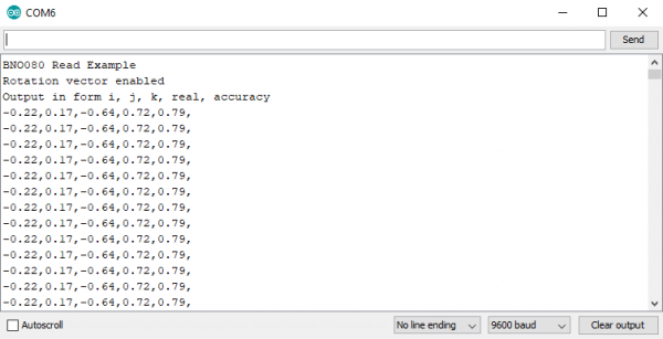
language:c float quatI = myIMU.getQuatI(); float quatJ = myIMU.getQuatJ(); bladder quatK = myIMU.getQuatK(); bladder quatReal = myIMU.getQuatReal(); bladder quatRadianAccuracy = myIMU.getQuatRadianAccuracy(); Printing the rotation vector is and so as easy as using a few Serial.print(quatI, 2) statements. Uploading the code and opening the Series Monitor to a baud rate of 9600 should yield an output similar to the below paradigm.
Example 2 - Accelerometer
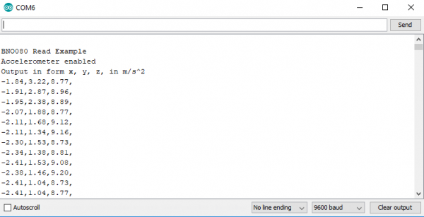
Examples 2 deals with pulling the accelerometer values from our sensor to figure out how it is moving. To get started, open up up Example2-Accelerometer under File > Examples > SparkFun BNO080 Cortex Based IMU > Example2-Accelerometer. At first glance, you'll discover that the style we set upwardly our IMU is virtually identical to the outset instance. The ane difference existence in our setup(), where we call myIMU.enableAccelerometer(50); instead of myIMU.enableRotationVector(fifty); which has the accelerometer report a value every 50 ms. Nosotros once again obtain and output our data in our void loop() by waiting for data using myIMU.dataAvailable(). In one case data is available we employ the following lines of code to get our x, y, and z acceleration values.
language:c float x = myIMU.getAccelX(); float y = myIMU.getAccelY(); float z = myIMU.getAccelZ(); We can then print these values to get our dispatch vector, uploading the code, and opening the Serial Monitor to a baud rate of 9600 should yield an output like to the beneath paradigm.
Example 3 - Gyro
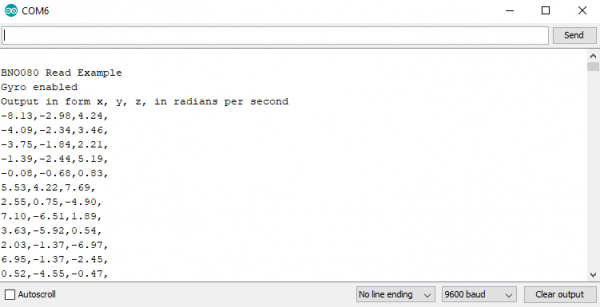
In example iii, we'll pull values from the IMU'south gyroscope to get a vector for our angular velocity. To get started, open up Example3-Gyro nether File > Examples > SparkFun BNO080 Cortex Based IMU > Example3-Gyro. The differences between this example and example 1 are very similar to the differences between examples ane & 2. Nosotros initialize the sensor the exact same way every bit example 1 simply calling myIMU.enableGyro(l); instead of myIMU.enableRotationVector(fifty); to have the gyro report information technology's value every fifty ms. Nosotros once again obtain and output our data in our void loop() by waiting for data using myIMU.dataAvailable(). Once data is available, we use the following lines of code to get our x, y, and z gyroscope values.
language:c float ten = myIMU.getGyroX(); float y = myIMU.getGyroY(); float z = myIMU.getGyroZ(); We can then print these values to get our gyroscope angular velocity vector, uploading the code, and opening the Serial Monitor to a baud rate of 9600 should yield an output similar to the below epitome.
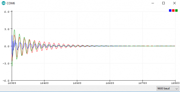
Also, bank check out the values in a graph by opening the Series Plotter to the same baud rate to see the readings from each gyroscope aqueduct plotted against each other. Rotate the IMU and meet how the values answer, I got the following output but letting the IMU swing on its cable.
Example 4 - Magnetometer
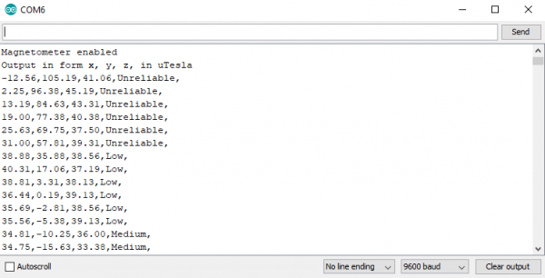
The post-obit case will get us reading a vector for the magnetic field. To become started, open up up Example4-Magnetometer under File > Examples > SparkFun BNO080 Cortex Based IMU > Example4-Magnetometer. The differences betwixt this case and instance ane are very similar to the differences betwixt examples ane & 2, are you starting to see a pattern hither? Nosotros initialize the sensor the verbal same way equally example one only calling myIMU.enableMagnetometer(50); instead of myIMU.enableRotationVector(50); to have the magnetometer written report it's value every 50 ms. We once again obtain and output our data in our void loop() by waiting for data using myIMU.dataAvailable(). Once data is available we use the following lines of code to get our x, y, and z magnetometer values. We likewise obtain the uncertainty in the magnetometer.
language:c bladder 10 = myIMU.getMagX(); bladder y = myIMU.getMagY(); bladder z = myIMU.getMagZ(); byte accuracy = myIMU.getMagAccuracy(); Nosotros can and then impress these values to go our magnetometer vector, uploading the code, and opening the Serial Monitor to a baud charge per unit of 9600 should yield an output similar to the below image.
Example 5 - Step Counter
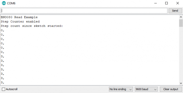
The BNO080 has some actually neat built in features due to its built in Cortex. One of these is a built in step counter. To get started with this pedometer, open up Example5-StepCounter nether File > Examples > SparkFun BNO080 Cortex Based IMU > Example5-StepCounter. The differences between this instance and example 1 are very similar to the differences in the previous examples. Nosotros initialize our step counter function with a lower sample charge per unit than our previous functions as nosotros don't wait steps to happen at every bit loftier of a rate. Due to this, we call myIMU.enableStepCounter(500) to allow for a half a second in between reports. Nosotros one time again obtain and output our information in our void loop() by waiting for data using myIMU.dataAvailable(). One time data is available, we pull the corporeality of steps from the IMU using unsigned int steps = myIMU.getStepCount() to initialize and populate an unsigned int with the step count. We then print this value to our serial monitor. Uploading the code and opening the Serial Monitor to a baud rate of 9600 should yield an output like to the below image.
Instance 6 - Metadata
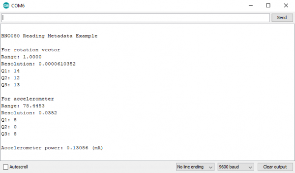
This example shows united states how to remember the static metadata from the dissimilar sensors in the IMU. To go started, open upward Example6-Metadata under File > Examples > SparkFun BNO080 Cortex Based IMU > Example6-Metadata. Notice how this example has an empty void loop()? Everything only happens once in our setup() loop. To get the metadata for a sensor, we only pass its respective FRS_RECORD_ID into getRange(), getResolution(), getQ1(), getQ2(), and getQ3() to remember the metadata for a sensor. The dissimilar FRS_RECORD_ID variables are shown below.
linguistic communication:c #ascertain FRS_RECORDID_ACCELEROMETER 0xE302 #define FRS_RECORDID_GYROSCOPE_CALIBRATED 0xE306 #define FRS_RECORDID_MAGNETIC_FIELD_CALIBRATED 0xE309 #define FRS_RECORDID_ROTATION_VECTOR 0xE30B These are so used like and then to print the different parts of each sensors metadata. For a little bit more on metadata, cheque out folio 29 of the Reference Manual. Uploading the lawmaking and opening the Serial Monitor to a baud rate of 9600 should yield an output similar to the below image.
Example 7 - Stability Classifier
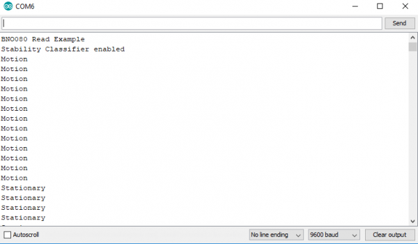
This instance sketch allows united states of america to use the built in stability classifier to figure out how stable the IMU is. To get started, open up upward Example7-StabilityClassifier under File > Examples > SparkFun BNO080 Cortex Based IMU > Example7-StabilityClassifier. This example is very similar to our first few examples in that we must call myIMU.enableStabilityClassifier(l); in our setup() function to take the stability classifier report its data every fifty ms. Notwithstanding, we also need to phone call myIMU.calibrateGyro() in our setup() office to enable all of our stability classification outputs. We so bank check if information is available using myIMU.dataAvailable(). If it is, nosotros pull the stability classification (a number from 0-5 using myIMU.getStabilityClassifier() ) and output the text corresponding to the classification. The code that does this in the void loop() is shown beneath. Also, take note of which number corresponds to which activity.
language:c if (myIMU.dataAvailable() == true) { byte classification = myIMU.getStabilityClassifier(); if(classification == 0) Serial.impress(F("Unknown nomenclature")); else if(nomenclature == 1) Series.impress(F("On table")); else if(classification == ii) Serial.print(F("Stationary")); else if(classification == 3) Series.print(F("Stable")); else if(nomenclature == 4) Serial.print(F("Motion")); else if(classification == v) Serial.impress(F("[Reserved]")); Series.println(); } Uploading the lawmaking and opening the Serial Monitor to a baud rate of 9600 should yield an output similar to the below epitome.
Example 8 - Action Classifier
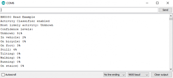
The activity classifier is somewhat similar to the stability classifier in that it uses the on-board cortex to decide what activity the IMU is doing. To become started, open Example8-ActivityClassifier under File > Examples > SparkFun BNO080 Cortex Based IMU > Example8-ActivityClassifier. To ready the activity classifier, we demand to tell the IMU which activities to look for. We do this using a 32-bit word. There are merely 8 possible activities at the moment, so we set our give-and-take enableActivities = 0x1F to enable everything. The activity classifier also gives a confidence level in each activity. To store these confidences, we create a variable byte activityConfidences[9] in a higher place our setup() function. Then, we can set upward the activeness classifier in our setup() function past calling myIMU.enableActivityClassifier(50, enableActivities, activityConfidences);. Using this office enables the activeness classifier with 50 ms betwixt reports, activities specified past enableActivities, and their confidences are stored in activityConfidences. We and then check if data is available using myIMU.dataAvailable(). If it is, we pull the activity classification (a number from 0-9 using myIMU.getActivityClassifier()) and output the text corresponding to the classification. The code that does this is shown below. Accept note of which number corresponds to which activity.
linguistic communication:c void loop() { //Await for reports from the IMU if (myIMU.dataAvailable() == truthful) { //getActivityClassifier will modify our activityConfidences array //It volition return the most likely activity likewise. byte mostLikelyActivity = myIMU.getActivityClassifier(); Series.print("Nigh probable activeness: "); printActivityName(mostLikelyActivity); Serial.println(); Serial.println("Conviction levels:"); for(int x = 0 ; x < 9 ; 10++) { printActivityName(ten); Series.print(F(") ")); Series.print(activityConfidences[x]); Serial.print(F("%")); Serial.println(); } Serial.println(); } } //Given a number between 0 and 8, print the name of the activity //Run into page 73 of reference manual for activity list void printActivityName(byte activityNumber) { if(activityNumber == 0) Serial.print("Unknown"); else if(activityNumber == 1) Series.impress("In vehicle"); else if(activityNumber == 2) Series.impress("On cycle"); else if(activityNumber == 3) Serial.print("On foot"); else if(activityNumber == 4) Serial.print("Notwithstanding"); else if(activityNumber == five) Series.print("Tilting"); else if(activityNumber == half dozen) Serial.print("Walking"); else if(activityNumber == seven) Serial.print("Running"); else if(activityNumber == 8) Serial.impress("On stairs"); } The output of this code should look something like the beneath paradigm.
Example 9 - Calibrate
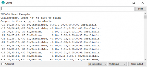
When moving betwixt different magnetic environments (different rooms, indoors, outdoors, etc...), it might be necessary to recalibrate your IMU to obtain the best readings. In order to do this, we'll run a calibration role,. To go started, open upwardly Example9-Calibrate nether File > Examples > SparkFun BNO080 Cortex Based IMU > Example9-Calibrate. In our setup office, we telephone call the part myIMU.calibrateAll() to begin calibration of our sensor. We too demand to make sure the we enable our game rotation vector and magnetometer equally these are necessary for computing the calibration of the magnetometer. Become alee and upload the code to the IMU and open the serial monitor to 9600 baud. Take a look at your output and look for the calibration status. This should probably say Unreliable. Brand sure you lot're in a clean magnetic environment and go through the calibration steps listed in the scale procedure. One time your sensor is calibrated, your accurateness should change from Unreliable to Medium or High. After calibration, ship an southward to your microcontroller over the serial monitor to run the following code and relieve the calibration.
language:c if(incoming == 'southward') { myIMU.saveCalibration(); //Saves the current dynamic scale data (DCD) to retention myIMU.endCalibration(); //Turns off all calibration Series.println("Scale ended"); } } Your Serial Monitor should wait something like the following image when the sensor is being calibrated. Remember, when your confidence levels are satisfactory, send an s to save the calibration.
Example 10 - Print Packet
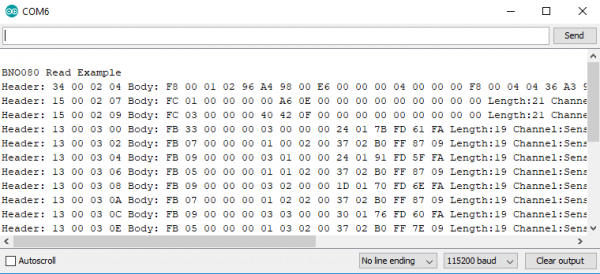
Sometimes information technology's easier to await at the raw data coming from the sensor for debugging purposes. This case shows you how to exercise just that. To get started, open up upwardly Example10-PrintPacket under File > Examples > SparkFun BNO080 Cortex Based IMU > Example10-PrintPacket. In our setup, we set up the sensors that we would like to use (in this instance, we'll prepare the magnetometer and accelerometer with 1000 ms sample rates). Since nosotros're most likely debugging in this mode, we'll too call myIMU.enableDebugging(Serial). Our void loop() then simply listens for and prints packets using the beneath code.
linguistic communication:c void loop() { //Look for reports from the IMU if (myIMU.receivePacket() == truthful) { myIMU.printPacket(); } } Your Serial Monitor should expect something similar the following epitome with this case code uploaded. Brand certain to alter the baud rate to 115200 equally opposed to 9600 like the previous examples.
Example xi - Avant-garde Configuration
The final instance just shows the states how to configure the sensor on different addresses and I2C buses. To get started, open Example11-AdvancedConfig nether File > Examples > SparkFun BNO080 Cortex Based IMU > Example11-AdvancedConfig. This is simply a matter of setting upwardly the sensor differently. Instead of calling myIMU.begin() with no arguments, nosotros phone call it as myIMU.begin(0x4A, Wire1). If we've pulled the SI pin high, the accost volition exist 0x4B. We can likewise prepare the sensor on a unlike IiiC bus if by passing in Wire2 in place of Wire1.
Bonus Example - Serial Cube Visualizer
Note: Processing is a software that enables visual representation of data, among other things. If you've never dealt with Processing before, we recommend you also check out the Arduino to Processing tutorial. Follow the below button to become alee and download and install Processing.
This extra instance isn't included in the library as it requires Processing. To catch it, go ahead and download or clone the BNO080 Github Repo.
Processing listens for serial data, so nosotros'll demand to become our Arduino producing serial data that makes sense to Processing. The required Arduino sketch is located in Qwiic_IMU_BNO080 > Software > Serial_Cube_Rotate > Serial_Cube_Rotate.ino. This sketch merely prints a listing of our quaternions separated past a comma over serial for Processing to listen to.
Once this sketch is uploaded, we need to tell Processing how to plow this information into a visualization. The Processing sketch to do this is located i folder to a higher place the Arduino sketch, in Qwiic_IMU_BNO080 > Software > Serial_Cube_Rotate.pde. Open the Serial_Cube_Rotate file in Processing. Before running the sketch, we'll need to download ToxicLibs, a library used for computational design. To do this, get to Sketch > Import Library... > Add Library.... Then search for and download ToxicLibs . Attempting to run the Processing sketch will show usa available serial ports in the debug window from this line of code.
language:c myPort = new Serial(this, Serial.listing()[0], 115200); Identify which series port your Arduino is on. For instance, my RedBoard is on COM6, which corresponds to [one] in the paradigm below, so I volition need to change 0 to 1 in the post-obit line to ensure Processing is listening to the correct serial port.
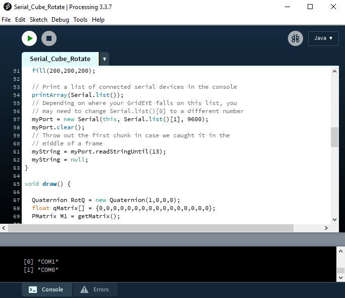
Once we've washed this, nosotros should be able to run the Processing sketch and it volition give us a nice visualization of how our IMU is oriented in 3D infinite as a cube. Endeavor rotating the IMU to meet how it responds. You should get a neat little output like the i in the beneath GIF.
Resources and Going Further
Thanks for reading! We're excited to see what you build with the Qwiic VR IMU. If you're left needing more BNO080-related documentation, check out some of these resource:
- Schematic (PDF) -- PDF schematic of the Qwiic VR IMU (BNO080).
- Hawkeye Files (Zero) -- PCB design files for the Qwiic VR IMU (BNO080).
- BNO080 Datasheet (PDF) -- Loads of data nearly the Qwiic VR IMU (BNO080) electric characteristics, registers, communication specifications, and more.
- Reference Transmission
- Sensor Hub Transport Protocol
- Sensor Calibration Procedure
- Qwiic Landing Page
- GitHub Repos
- Product Repo -- Design files and case code all related to the Qwiic VR IMU (BNO080).
- Library GitHub Repo
- Arduino Library - Arduino library for the Qwiic VR IMU (BNO080).
Need some inspiration for your side by side projection? Check out some of these related tutorials:
Dungeons and Dragons Dice Gauntlet
A playful, geeky tutorial for a leather bracer that uses a LilyPad Arduino, LilyPad accelerometer, and seven segment display to roll virtual 4, 6, 8, 10, 12, 20, and 100 side die for gaming.
9DoF Razor IMU M0 Hookup Guide
How to use and re-program the 9DoF Razor IMU M0, a combination of ATSAMD21 ARM Cortex-M0 microprocessor and MPU-9250 9DoF-in-a-bit.
Or bank check out this blog post for ideas:
Source: https://learn.sparkfun.com/tutorials/qwiic-vr-imu-bno080-hookup-guide/all